Load balancing AGFA HealthCare Enterprise Imaging
Updated on February 3, 2026
•
Published on August 19, 2024
Benefits of load balancing AGFA HealthCare Enterprise Imaging
The main benefits of load balancing AGFA HealthCare Enterprise Imaging are High Availability (HA), optimized performance, and scalability.
- High Availability (HA): Load balancing is crucial for achieving High Availability (HA) by eliminating single points of failure. It distributes imaging and application traffic (like DICOM studies) across multiple AGFA servers or clusters. If one server fails, the load balancer automatically redirects all traffic to the remaining healthy servers, ensuring zero downtime and continuous access to patient images and data. This seamless failover mechanism is vital in healthcare, where timely access to diagnostic images is critical for urgent patient care.
- Optimized performance: Load balancing ensures that system performance remains stable and fast, especially during peak usage. It routes incoming requests (e.g., image retrievals, study uploads) to the least-loaded or best-performing server, preventing any single server from becoming a bottleneck. This is particularly important for DICOM traffic, which involves large imaging files. By efficiently distributing the workload across the entire server infrastructure, it helps accelerate image processing and viewing times, which directly contributes to faster report turnaround and better patient care.
- Scalability: As healthcare organizations grow, load balancing provides the flexibility to scale the imaging infrastructure easily. It allows IT to add or remove application servers (nodes) from the AGFA Enterprise Imaging system without any service disruption. This makes it easy to handle growing data volumes and an increasing number of users over time. Servers can be temporarily taken offline for maintenance or upgrades (like software patching) without interrupting clinical workflows, as the load balancer simply redirects all traffic away from the maintenance target.
About AGFA HealthCare Enterprise Imaging
AGFA HealthCare Enterprise Imaging is designed to build a connected, collaborative, and scalable community of care.
This one-of-a-kind, seamless and secure platform makes this a reality through the creation of an Imaging Health Network™ (IHN). There, images are available 24/7 to all members of the care team — no matter where they are, or what kind of device they are working from.
How to load balance AGFA HealthCare Enterprise Imaging
The load balancer can be deployed in four fundamental ways: Layer 4 DR mode, Layer 4 NAT mode, Layer 4 SNAT mode, and Layer 7 Reverse Proxy (Layer 7 SNAT mode).
For AGFA HealthCare Enterprise Imaging, Layer 7 Reverse Proxy is recommended.
Virtual service (VIP) requirements
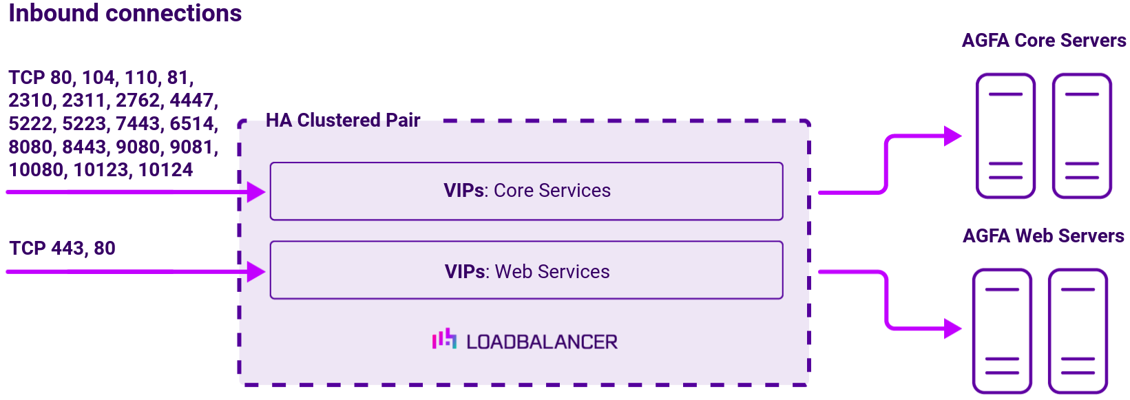
To provide load balancing and HA for AGFA HealthCare Enterprise Imaging, the following VIPs are required:
| Ref. | VIP Name | Mode | Port(s) | Persistence Mode | Health Check |
|---|---|---|---|---|---|
| VIP 1 | CoreServerClient-80 | Layer 7 Reverse Proxy (HTTP) | 80 | HTTP Cookie | HTTP (GET) |
| VIP 2 | CoreServerDICOM-104 | Layer 7 Reverse Proxy (TCP) | 104 | None | HTTP (GET) |
| VIP 3 | CoreServerDICOM-110 | Layer 7 Reverse Proxy (TCP) | 110 | None | HTTP (GET) |
| VIP 4 | CoreServer-443 | Layer 7 Reverse Proxy (HTTP) | 81 | HTTP Cookie | HTTPS (GET) |
| VIP 5 | CoreServerHL7-2310 | Layer 7 Reverse Proxy (TCP) | 2310 | None | Connect to Port |
| VIP 6 | CoreServerHL7-2311 | Layer 7 Reverse Proxy (TCP) | 2311 | None | Connect to Port |
| VIP 7 | CoreServerDICOM-2762 | Layer 7 Reverse Proxy (TCP) | 2762 | None | HTTP (GET) |
| VIP 8 | CoreServerClient-4447 | Layer 7 Reverse Proxy (TCP) | 4447 | None | HTTP (GET) |
| VIP 9 | CoreServerClient-5222 | Layer 7 Reverse Proxy (TCP) | 5222 | None | Connect to Port |
| VIP 10 | CoreServerClient-5223 | Layer 7 Reverse Proxy (TCP) | 5223 | None | Connect to Port |
| VIP 11 | CoreServerClient-7443 | Layer 7 Reverse Proxy (TCP) | 7443 | None | Connect to Port |
| VIP 12 | CoreServerARR-6514 | Layer 7 Reverse Proxy (TCP) | 6514 | None | Connect to Port |
| VIP 13 | CoreServerClient-8080 | Layer 7 Reverse Proxy (HTTP) | 8080 | HTTP Cookie | HTTP (GET) |
| VIP 14 | CoreServerClient-8443 | Layer 7 Reverse Proxy (HTTP) | 8443 | Source IP | HTTPS (GET) |
| VIP 15 | CoreServerClient-9080 | Layer 7 Reverse Proxy (HTTP) | 9080 | Source IP | |
| VIP 16 | CoreServerClient-9081 | Layer 7 Reverse Proxy (HTTP) | 9081 | Source IP | HTTP (GET) |
| VIP 17 | CoreServerClient-10080 | Layer 7 Reverse Proxy (HTTP) | 10080 | Source IP | HTTP (GET) |
| VIP 18 | CoreServerClient-10123 | Layer 7 Reverse Proxy (TCP) | 10123 | Source IP | Connect to Port |
| VIP 19 | CoreServerClient-10124 | Layer 7 Reverse Proxy (TCP) | 10124 | Source IP | Connect to Port |
| VIP 20 | WebServer-withXero | Layer 7 Reverse Proxy (TCP) | 443 | None | HTTPS (GET) |
| VIP 21 | WebServer-withoutXero | Layer 7 Reverse Proxy (HTTP) | 80 | HTTP Cookie | HTTPS (GET) |
Load balancing deployment concept
Once the load balancer is deployed, clients connect to the Virtual Services (VIPs) rather than connecting directly to the AGFA HealthCare Enterprise Imaging servers. These connections are then load balanced across the AGFA HealthCare Enterprise Imaging servers to distribute the load according to the load balancing algorithm selected.
Topology
Layer 7 SNAT mode can be deployed using either a one-arm or two-arm configuration. For two-arm deployments, eth1 is typically used for client side connections and eth0 is used for Real Server connections, although this is not mandatory since any interface can be used for any purpose. For more on one and two-arm topology see Topologies & Load Balancing Methods.
About Layer 7 Reverse Proxy
Layer 7 Reverse Proxy uses a proxy (HAProxy) at the application layer. Inbound requests are terminated on the load balancer and HAProxy generates a new corresponding request to the chosen Real Server. As a result, Layer 7 is typically not as fast as the Layer 4 methods. Layer 7 is typically chosen when either enhanced options such as SSL termination, cookie based persistence, URL rewriting, header insertion/deletion etc. are required, or when the network topology prohibits the use of the Layer 4 methods. The image below shows an example network diagram for this mode.
The image below shows an example Layer 7 Reverse Proxy network diagram:

Because Layer 7 Reverse Proxy is a full proxy, Real Servers in the cluster can be on any accessible network including across the Internet or WAN.
Layer 7 Reverse Proxy is not transparent by default, i.e. the Real Servers will not see the source IP address of the client, they will see the load balancer’s own IP address by default, or any other local appliance IP address if preferred (e.g. the VIP address). This can be configured per Layer 7 VIP. If required, the load balancer can be configured to provide the actual client IP address to the Real Servers in 2 ways. Either by inserting a header that contains the client’s source IP address, or by modifying the Source Address field of the IP packets and replacing the IP address of the load balancer with the IP address of the client. For more information on these methods please refer to Transparency at Layer 7.
Requires no mode-specific configuration changes to the load balanced Real Servers.
Port translation is possible with Layer 7 Reverse Proxy, e.g. VIP:80 → RIP:8080 is supported.
You should not use the same RIP:PORT combination for Layer 7 Reverse Proxy VIPs and Layer 4 SNAT mode VIPs because the required firewall rules conflict.