Benefits of load balancing Boomi Blueprint
The top three reasons to load balance a Boomi runtime environment (like a Boomi Molecule or a runtime cluster often leveraged within the Boomi Blueprint framework) are High Availability, scalability, and enhanced performance:
- High Availability (HA): Load balancing ensures that your mission-critical integration processes remain operational even if one of the runtime nodes fails. A load balancer or the Boomi Molecule’s built-in clustering mechanism monitors the health of all nodes. If a node (Atom) fails or goes down for maintenance, the load balancer automatically redirects traffic and processes to the remaining healthy nodes. This failover capability is crucial for high-priority integrations, minimizing service disruption and ensuring that critical business operations continue without manual intervention.
- Scalability: Load balancing allows your Boomi integration platform to handle growth in data volume and transaction load. As your business grows or your integration demands increase (e.g., during peak seasons or high-volume data migrations), you can easily add more Atom nodes to the cluster (Molecule) to handle the increased workload. The load balancer automatically distributes new work across these additional nodes, providing a flexible and elastic capacity that prevents any single server from becoming a bottleneck.
- Enhanced performance: By distributing the workload, load balancing prevents resource contention and optimizes the execution of integration processes. Processes are intelligently spread across all available nodes, preventing any single node from being overloaded with a high volume of simultaneous requests. This distribution optimizes resource utilization (CPU, memory) across the cluster, which leads to faster overall processing of integration flows and a significant improvement in the platform’s throughput.
About Boomi Blueprint
Boomi Blueprint is a framework developed by Boomi, an iPaaS provider.
It helps organizations plan, implement, and manage their integration and automation strategies effectively.
Why Loadbalancer.org for Boomi Blueprint?
Loadbalancer’s intuitive Enterprise Application Delivery Controller (ADC) is designed to save time and money with a clever, not complex, WebUI.
Easily configure, deploy, manage, and maintain our Enterprise load balancer, reducing complexity and the risk of human error. For a difference you can see in just minutes.
And with WAF and GSLB included straight out-of-the-box, there’s no hidden costs, so the prices you see on our website are fully transparent.
More on what’s possible with Loadbalancer.org.
How to load balance Boomi Blueprint
The load balancer can be deployed in four fundamental ways: Layer 4 DR mode, Layer 4 NAT mode, Layer 4 SNAT mode, and Layer 7 Reverse Proxy (Layer 7 SNAT mode).
For Boomi Blueprint, Layer 7 Reverse Proxy is recommended.
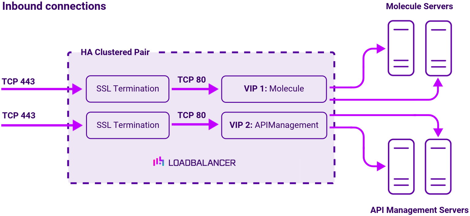
Virtual service (VIP) requirements
To provide load balancing and HA for Boomi Blueprint, the following VIPs are required:
| Ref. | VIP Name | Mode | Port | Persistence Mode | Health Check |
|---|---|---|---|---|---|
| VIP 1 | Molecule | Layer 7 Reverse Proxy | 80 | None | HTTP (GET) |
| VIP 2 | APIManagement | Layer 7 Reverse Proxy | 80 | Source IP | HTTP (GET) |
Load balancing deployment concept
Load balancing topology
Layer 7 Reverse Proxy can be deployed using either a one-arm or two-arm configuration. For two-arm deployments, eth1 is typically used for client side connections and eth0 is used for Real Server connections, although this is not mandatory since any interface can be used for any purpose.
For more on one and two-arm topology see Topologies & Load Balancing Methods.
About Layer 7 Reverse Proxy load balancing
Layer 7 Reverse Proxy uses a proxy (HAProxy) at the application layer. Inbound requests are terminated on the load balancer and HAProxy generates a new corresponding request to the chosen Real Server. As a result, Layer 7 is typically not as fast as the Layer 4 methods. Layer 7 is typically chosen when either enhanced options such as SSL termination, cookie based persistence, URL rewriting, header insertion/deletion etc. are required, or when the network topology prohibits the use of the Layer 4 methods.
The image below shows an example Layer 7 Reverse Proxy network diagram:

Because Layer 7 Reverse Proxy is a full proxy, Real Servers in the cluster can be on any accessible network including across the Internet or WAN.
Layer 7 Reverse Proxy is not transparent by default, i.e. the Real Servers will not see the source IP address of the client, they will see the load balancer’s own IP address by default, or any other local appliance IP address if preferred (e.g. the VIP address).
This can be configured per Layer 7 VIP. If required, the load balancer can be configured to provide the actual client IP address to the Real Servers in 2 ways. Either by inserting a header that contains the client’s source IP address, or by modifying the Source Address field of the IP packets and replacing the IP address of the load balancer with the IP address of the client. For more information on these methods, please refer to Transparency at Layer 7 in the Enterprise Admin Manual.