Load balancing Cloudian HyperFile NAS Storage
Updated on October 23, 2025
•
Published on March 7, 2023
Benefits of load balancing Cloudian HyperFile NAS Storage
Load balancing Cloudian HyperFile NAS storage offers High Availability (HA), enhanced performance, and increased scalability:
- High Availability (HA): Load balancing is crucial for eliminating single points of failure in the NAS environment. By distributing client requests across multiple HyperFile nodes, the load balancer ensures continuous data access. If a primary HyperFile node fails or becomes unresponsive, the load balancer automatically redirects all traffic to the remaining healthy nodes, preventing downtime and service interruptions. This results in maximum uptime and data protection.
- Enhanced performance: Load balancing intelligently distributes the incoming file access and management workload across all available HyperFile nodes, preventing bottlenecks.
Traffic is directed to the least-utilized or most responsive servers, ensuring an even distribution of workload across the cluster. By preventing any single node from being overwhelmed, the load balancer helps maintain faster response times for client requests, delivering the maximum performance from the scale-out architecture. - Increased scalability: Load balancing simplifies the process of expanding the HyperFile environment to meet growing data demands. New HyperFile nodes can be seamlessly added to the cluster without affecting ongoing operations. The load balancer automatically starts including the new nodes in the traffic distribution pool. This provides a truly scalable environment that can grow from terabytes to petabytes, enabling organizations to manage massive amounts of unstructured data without service disruption.
About Cloudian HyperFile
Cloudian HyperFile is a scale-out NAS platform that provides file system protocols for clients and transparent data tiering to object storage (Cloudian HyperStore). Client applications write data to HyperFile which then manages the underlying storage tiers, leveraging its native information lifecycle management capabilities.
Why Loadbalancer.org for Cloudian HyperFile NAS?
Cloudian and Loadbalancer.org work together in partnership to reduce infrastructure complexity through intelligently designed and infinitely scalable network architecture. Users across many industries – including medical and media – are facing rapid increases in data, with storage demands intensifying as technologies progress.
Together they ensure customers can enjoy the benefits of NAS and object storage in their own data centers, thanks to indestructible, enterprise, scale-out solutions.
Loadbalancer’s intuitive Enterprise Application Delivery Controller (ADC) is also designed to save time and money with a clever, not complex, WebUI.
Easily configure, deploy, manage, and maintain our Enterprise load balancer, reducing complexity and the risk of human error. For a difference you can see in just minutes.
And with WAF and GSLB included straight out-of-the-box, there’s no hidden costs, so the prices you see on our website are fully transparent.
More on what’s possible with Loadbalancer.org.
How to load balance Cloudian HyperFile
The load balancer can be deployed in four fundamental ways: Layer 4 DR mode, Layer 4 NAT mode, Layer 4 SNAT mode, and Layer 7 Reverse Proxy (Layer 7 SNAT mode).
For Cloudian HyperFile, we recommend that Layer 4 Direct Routing (DR) mode is used. This mode offers the best possible performance since replies go directly from the Real Servers to the client, not via the load balancer. It’s also relatively simple to implement. Ultimately, the final choice does depend on your specific requirements and infrastructure.
If DR mode cannot be used, for example if the real servers are located in remote routed networks, then Layer 7 Reverse Proxy is recommended. If using NFS version 3 and below, Layer 4 DR mode should be used due to the wide range of ports that are used in these older versions of the NFS protocol.
Note: If the load balancer is deployed in AWS or Azure, Layer 7 Reverse Proxy must be used as Layer 4 direct routing is not currently possible on these platforms.
Virtual service (VIP) requirements
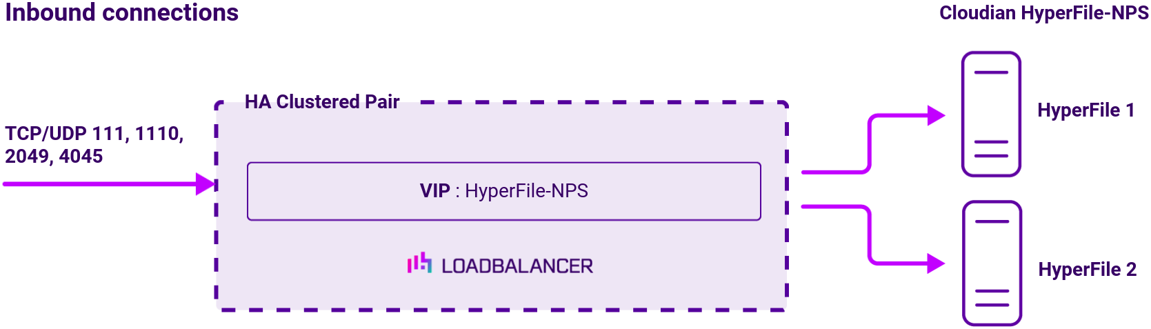
To provide load balancing and HA for Cloudian HyperFile a single VIP is used which covers all of the ports needed.
Load balancing deployment concept
To allow a Cloudian HyperFile deployment to be load balanced, the HyperFile nodes must be deployed in a multi-controller configuration sharing an NFS volume. Source IP address persistence is required to successfully load balance Cloudian HyperFile. This is true for both the Layer 4 DR mode and Layer 7 load balancing scenarios described in this document. To provide load balancing and HA for Cloudian HyperFile, a single VIP is used which covers all of the ports needed.
Note
The load balancer can be deployed as a single unit, although Loadbalancer.org recommends a clustered pair for resilience and high availability.
About Layer 4 DR mode load balancing
Layer 4 DR (Direct Routing) mode is a very high performance solution that requires little change to your existing infrastructure. The image below shows an example Layer 4 DR mode network diagram:
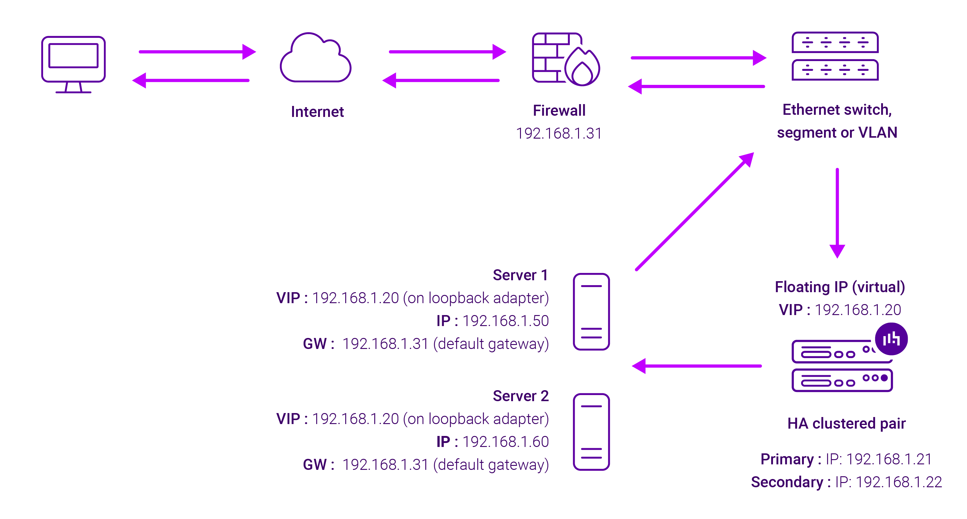
- DR mode works by changing the destination MAC address of the incoming packet to match the selected Real Server on the fly which is very fast
- When the packet reaches the Real Server it expects the Real Server to own the Virtual Services IP address (VIP). This means that you need to ensure that the Real Server (and the load balanced application) respond to both the Real Servers own IP address and the VIP
- The Real Server should not respond to ARP requests for the VIP. Only the load balancer should do this. Configuring the Real Servers in this way is referred to as Solving the ARP Problem. Please refer to the instructions in section Configuring for Layer 4 DR Mode in the Deployment Guide for more information
- On average, DR mode is 8 times quicker than NAT for HTTP, 50 times quicker for Terminal Services and much, much faster for streaming media or FTP
- The load balancer must have an Interface in the same subnet as the Real Servers to ensure layer 2 connectivity required for DR mode to work
- The VIP can be brought up on the same subnet as the Real Servers, or on a different subnet provided that the load balancer has an interface in that subnet
- Port translation is not possible in DR mode i.e. having a different RIP port than the VIP port
- DR mode is transparent, i.e. the Real Server will see the source IP address of the client
About Layer 7 Reverse Proxy load balancing
Layer 7 Reverse Proxy uses a proxy (HAProxy) at the application layer. Inbound requests are terminated on the load balancer and HAProxy generates a new corresponding request to the chosen Real Server. As a result, Layer 7 is typically not as fast as the Layer 4 methods. Layer 7 is typically chosen when either enhanced options such as SSL termination, cookie based persistence, URL rewriting, header insertion/deletion etc. are required, or when the network topology prohibits the use of the Layer 4 methods.
The image below shows an example Layer 7 Reverse Proxy network diagram:

Because Layer 7 Reverse Proxy is a full proxy, Real Servers in the cluster can be on any accessible network including across the Internet or WAN.
Layer 7 Reverse Proxy is not transparent by default, i.e. the Real Servers will not see the source IP address of the client, they will see the load balancer’s own IP address by default, or any other local appliance IP address if preferred (e.g. the VIP address).
This can be configured per Layer 7 VIP. If required, the load balancer can be configured to provide the actual client IP address to the Real Servers in 2 ways. Either by inserting a header that contains the client’s source IP address, or by modifying the Source Address field of the IP packets and replacing the IP address of the load balancer with the IP address of the client. For more information on these methods, please refer to Transparency at Layer 7 in the Enterprise Admin Manual.