Load balancing Insignia Medical Systems
Updated on November 25, 2025
•
Published on March 6, 2023
Benefits of load balancing Insignia Medical systems
Load balancing Insignia Medical systems (such as their PACS and VNA solutions) provides some critical benefits:
- High Availability (HA): Load balancing ensures that if one server or application component fails, traffic is automatically and seamlessly redirected to the remaining healthy servers. This is crucial for medical systems like PACS, guaranteeing continuous access to critical patient images and reports, which is essential for 24/7 patient care and preventing disruptions to clinical workflows.
- Scalability: Load balancing intelligently distributes increasing volumes of DICOM study data and user requests across multiple clustered servers. This prevents any single server from being overwhelmed, reducing bottlenecks, and maintaining fast, optimal performance for clinicians, even in environments with constantly growing imaging demands. It allows organizations to scale their operations cost-effectively.
- Enhanced efficiency and resource utilization: By distributing the workload evenly, load balancing ensures that all clustered servers are utilized efficiently. This optimizes computing resources, reduces server strain, and helps accelerate the processing and delivery of imaging studies, contributing to overall enhanced workflow efficiency in high-volume healthcare environments.
About Insignia Medical systems
The company formerly known as Insignia Medical Systems was acquired by Intelerad Medical Systems in 2021.
While Insignia Medical Systems still has a presence, its solutions (such as InSight PACS and InStore VNA) are now part of the Intelerad portfolio. For more on Intelerad see their product suites.
Why Loadbalancer.org for Insignia Medical systems?
Loadbalancer’s intuitive Enterprise Application Delivery Controller (ADC) is designed to save time and money with a clever, not complex, WebUI.
Easily configure, deploy, manage, and maintain our Enterprise load balancer, reducing complexity and the risk of human error. For a difference you can see in just minutes.
And with WAF and GSLB included straight out-of-the-box, there’s no hidden costs, so the prices you see on our website are fully transparent.
More on what’s possible with Loadbalancer.org.
How to load balance Insignia Medical systems
The load balancer can be deployed in four fundamental ways: Layer 4 DR mode, Layer 4 NAT mode, Layer 4 SNAT mode, and Layer 7 Reverse Proxy (Layer 7 SNAT mode).
In the attached deployment guide, Layer 4 DR mode is used for the DICOM VIP and Layer 7 Reverse Proxy is used for the HL7 VIP.
Where possible we recommend that Layer 4 Direct Routing (DR) mode is used. This mode offers the best possible performance since replies go directly from the Real Servers to the client, not via the load balancer. It’s also relatively simple to implement.
Note
If you are using Microsoft Windows Real Servers (i.e. the backend servers) make sure that Windows NLB (Network Load Balancing) is completely disabled to ensure that this does not interfere with the operation of the load balancer.
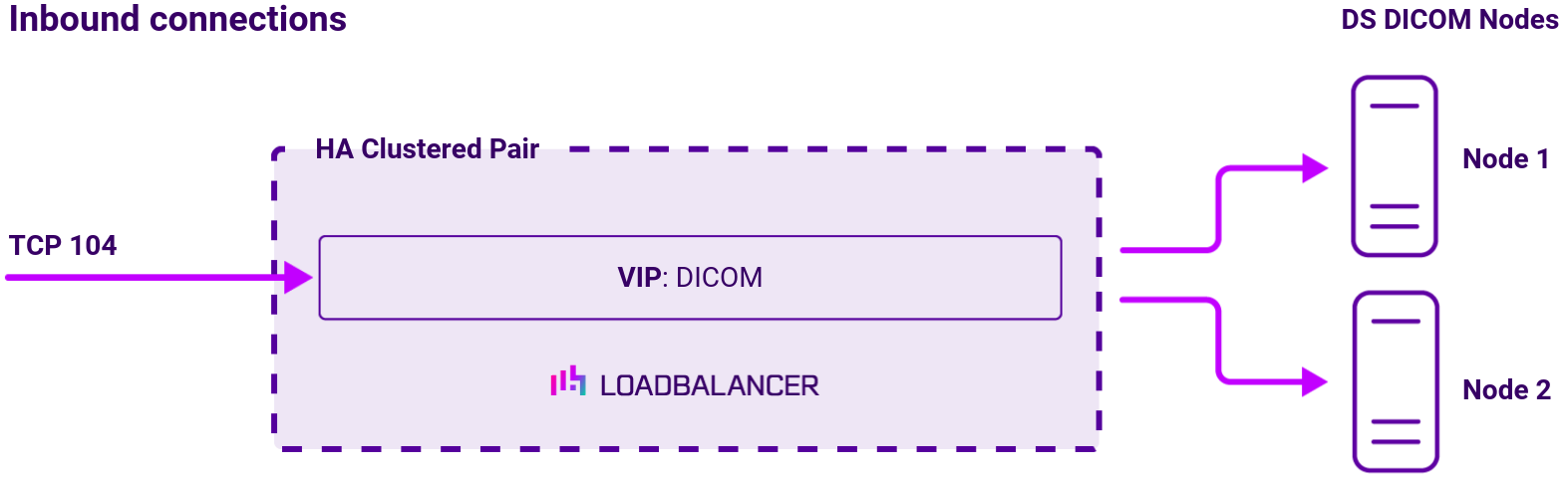
Virtual service (VIP) requirements
To provide resilience and high availability, multiple Virtual Services (VIPs) are configured for the various protocols and systems.
Clients and systems then connect to these VIPs rather than directly to the application servers.
Each VIP can be configured in one of the following ways:
- Load balanced mode: Load is distributed across all configured servers/endpoints
- Failover mode: The second server is used only when the first server/endpoint fails
Load balancing deployment method
About Layer 4 DR mode load balancing
One-arm direct routing (DR) mode is a very high performance solution that requires little change to your existing infrastructure.
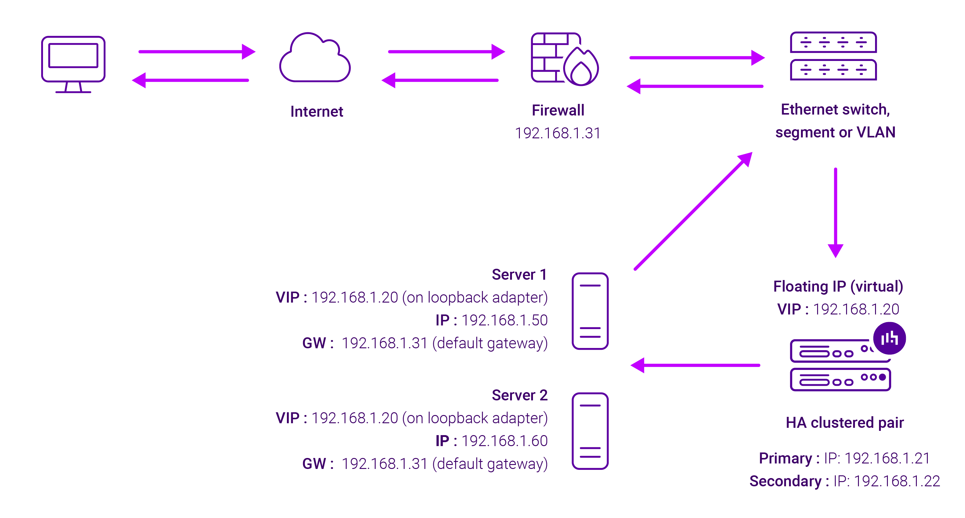
DR mode works by changing the destination MAC address of the incoming packet to match the selected Real Server on the fly which is very fast.
When the packet reaches the Real Server it expects the Real Server to own the Virtual Services IP address (VIP). This means that you need to ensure that the Real Server (and the load balanced application) respond to both the Real Server’s own IP address and the VIP.
The Real Servers should not respond to ARP requests for the VIP. Only the load balancer should do this. Configuring the Real Servers in this way is referred to as Solving the ARP problem.
On average, DR mode is 8 times quicker than NAT for HTTP, 50 times quicker for Terminal Services and much, much faster for streaming media or FTP.
The load balancer must have an Interface in the same subnet as the Real Servers to ensure Layer 2 connectivity required for DR mode to work.
The VIP can be brought up on the same subnet as the Real Servers, or on a different subnet provided that the load balancer has an interface in that subnet.
Port translation is not possible with DR mode, e.g. VIP:80 → RIP:8080 is not supported. DR mode is transparent, i.e. the Real Server will see the source IP address of the client.
About Layer 7 Reverse Proxy load balancing
Layer 7 Reverse Proxy uses a proxy (HAProxy) at the application layer. Inbound requests are terminated on the load balancer and HAProxy generates a new corresponding request to the chosen Real Server. As a result, Layer 7 is typically not as fast as the Layer 4 methods. Layer 7 is typically chosen when either enhanced options such as SSL termination, cookie based persistence, URL rewriting, header insertion/deletion etc. are required, or when the network topology prohibits the use of the Layer 4 methods.
The image below shows an example Layer 7 Reverse Proxy network diagram:

Because Layer 7 Reverse Proxy is a full proxy, Real Servers in the cluster can be on any accessible network including across the Internet or WAN.
Layer 7 Reverse Proxy is not transparent by default, i.e. the Real Servers will not see the source IP address of the client, they will see the load balancer’s own IP address by default, or any other local appliance IP address if preferred (e.g. the VIP address).
This can be configured per Layer 7 VIP. If required, the load balancer can be configured to provide the actual client IP address to the Real Servers in 2 ways. Either by inserting a header that contains the client’s source IP address, or by modifying the Source Address field of the IP packets and replacing the IP address of the load balancer with the IP address of the client. For more information on these methods, please refer to Transparency at Layer 7 in the Enterprise Admin Manual.