Benefits of load balancing Kofax eCopy ShareScan
Load balancing Kofax eCopy ShareScan provides High Availability, scalability, and improved performance:
- High Availability (HA): Load balancing ensures that the eCopy ShareScan system remains accessible and operational even if one server fails. A load balancer constantly monitors the health of the multiple eCopy ShareScan servers. If one server becomes unavailable due to a hardware, network, or application issue, the load balancer automatically redirects all traffic to the remaining healthy servers. This failover capability minimizes downtime, ensuring users can continue to scan documents and access workflows without interruption.
- Scalability: Load balancing allows you to easily expand your system’s capacity to handle increased demand. As your organization grows or document processing requirements increase, you can simply add more eCopy ShareScan servers to the back-end pool. The load balancer instantly incorporates the new servers into the cluster. By distributing the load across multiple servers, the system can smoothly handle traffic spikes (e.g., during peak scanning times) without performance degradation or system overloads on any single machine.
- Improved performance: By distributing incoming requests, load balancing prevents any single server from becoming a bottleneck, leading to faster response times for users. The load balancer uses algorithms to ensure that the document capture and processing workload (including document creation and OCR phases) is evenly distributed across all available ShareScan servers. Spreading the workload prevents servers from being overworked, which results in better overall system responsiveness and faster processing times for users scanning documents at the Multi-Function Printers (MFPs).
About Kofax eCopy ShareScan
Kofax eCopy ShareScan 6.2 is a Multi-function Printer (MFP) document capture solution that enables MFP users to engage their business systems and processes by completely automating the document capture processes. As a result, eCopy ShareScan simplifies MFP capture workflows and enables users to have advanced imaging capabilities.
The eCopy ShareScan software extends the capabilities of a wide range of digital copiers and scanners.
The primary function of the load balancer is to distribute inbound requests across multiple eCopy ShareScan servers. This allows administrators to configure multiple servers and easily share the load between them. Adding additional capacity as demand grows then becomes straight forward and can be achieved by simply adding additional eCopy ShareScan servers to the load balanced cluster.
Why Loadbalancer.org for Kofax eCopy ShareScan?
Loadbalancer’s intuitive Enterprise Application Delivery Controller (ADC) is designed to save time and money with a clever, not complex, WebUI.
Easily configure, deploy, manage, and maintain our Enterprise load balancer, reducing complexity and the risk of human error. For a difference you can see in just minutes.
And with WAF and GSLB included straight out-of-the-box, there’s no hidden costs, so the prices you see on our website are fully transparent.
More on what’s possible with Loadbalancer.org.
How to load balance Kofax eCopy ShareScan
The load balancer can be deployed in four fundamental ways: Layer 4 DR mode, Layer 4 NAT mode, Layer 4 SNAT mode, and Layer 7 Reverse Proxy (Layer 7 SNAT mode).
For Kofax eCopy ShareScan, Layer 4 DR mode and Layer 4 NAT mode are recommended.
These modes are described below and are used for the configurations presented in this guide. For configuring using DR mode, please refer to Appliance & eCopy ShareScan Server Configuration – Using Layer 4 DR Mode, for configuring using NAT mode, refer to Appliance & eCopy ShareScan Server Configuration – Using Layer 4 NAT Mode.
When installing and setting up a ShareScan system, you must be familiar with the scanning devices that you will use with ShareScan, the ShareScan software components, and the basic installation and configuration workflow.
Ports and protocols
The following table shows the ports that are normally used with eCopy ShareScan:
| Port | Protocol | Use |
|---|---|---|
| * | TCP | Testing load balancer configuration |
| 8080 | TCP/HTTP | HTTP eCopy Tomcat application |
| 443 | TCP/HTTPS | HTTPS eCopy Tomcat application |
| 9600 | TCP | Web based MFDs |
| 9261 | TCP | Embedded MFDs i.e. Ricoh and Canon |
Load balancing deployment concept
The following diagram illustrates how the load balancer is deployed with multiple eCopy ShareScan servers:
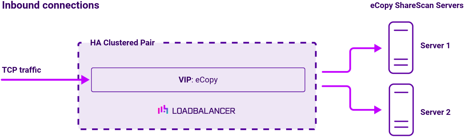
Note
The load balancer can be deployed as a single unit, although Loadbalancer.org recommends a clustered pair for resilience and high availability.
About Layer 4 DR mode load balancing
One-arm direct routing (DR) mode is a very high performance solution that requires little change to your existing infrastructure:
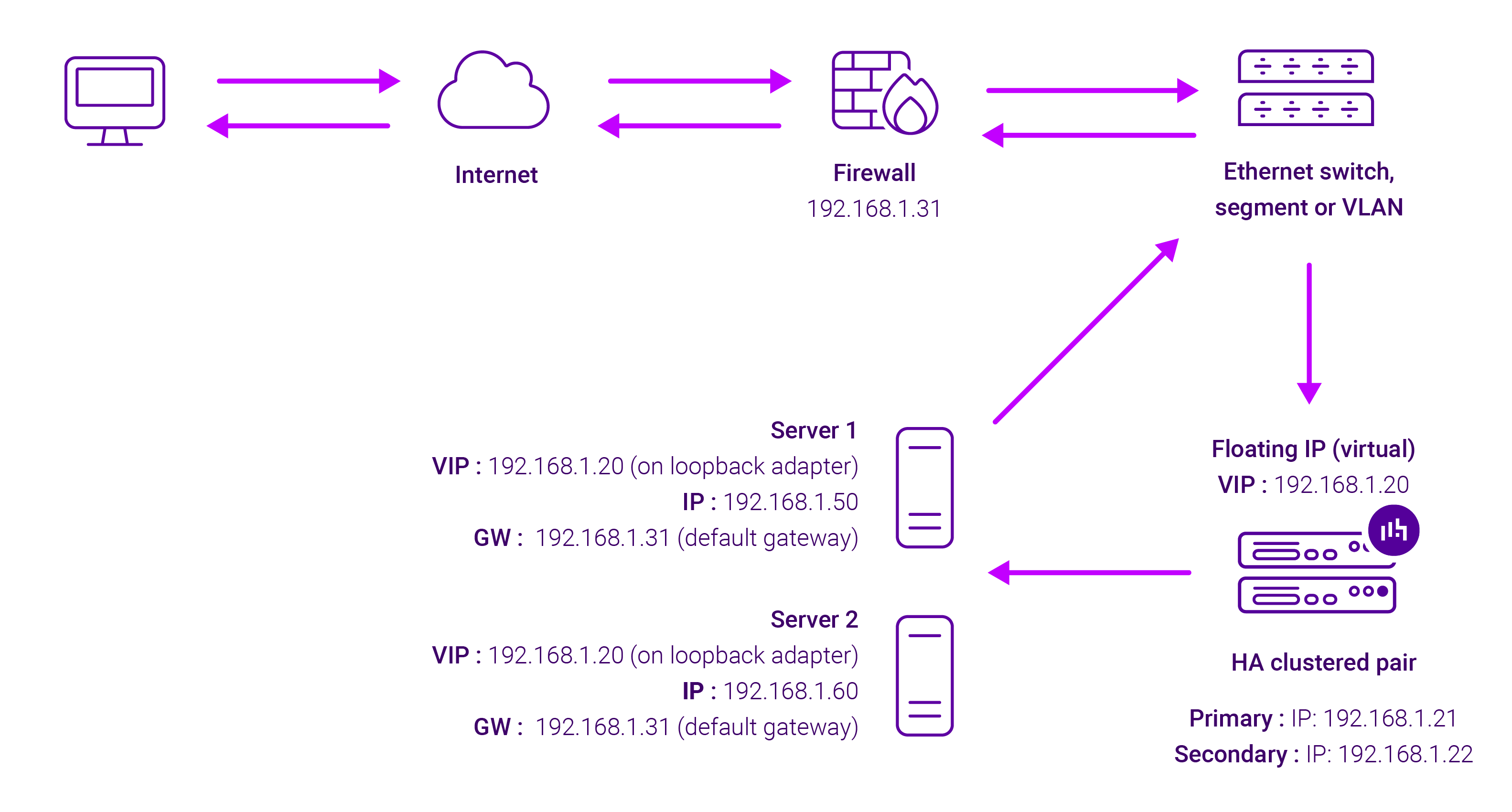
DR mode works by changing the destination MAC address of the incoming packet to match the selected Real Server on the fly which is very fast.
When the packet reaches the Real Server it expects the Real Server to own the Virtual Services IP address (VIP). This means that you need to ensure that the Real Server (and the load balanced application) respond to both the Real Server’s own IP address and the VIP.
The Real Servers should not respond to ARP requests for the VIP. Only the load balancer should do this. Configuring the Real Servers in this way is referred to as Solving the ARP problem.
On average, DR mode is 8 times quicker than NAT for HTTP, 50 times quicker for Terminal Services and much, much faster for streaming media or FTP.
The load balancer must have an Interface in the same subnet as the Real Servers to ensure Layer 2 connectivity required for DR mode to work.
The VIP can be brought up on the same subnet as the Real Servers, or on a different subnet provided that the load balancer has an interface in that subnet.
Port translation is not possible with DR mode, e.g. VIP:80 → RIP:8080 is not supported. DR mode is transparent, i.e. the Real Server will see the source IP address of the client.
About Layer 4 NAT mode load balancing
Layer 4 NAT mode is a high performance solution, although not as fast as Layer 4 DR mode. This is because real server responses must flow back to the client via the load balancer rather than directly as with DR mode. The image below shows an example network diagram for this mode:
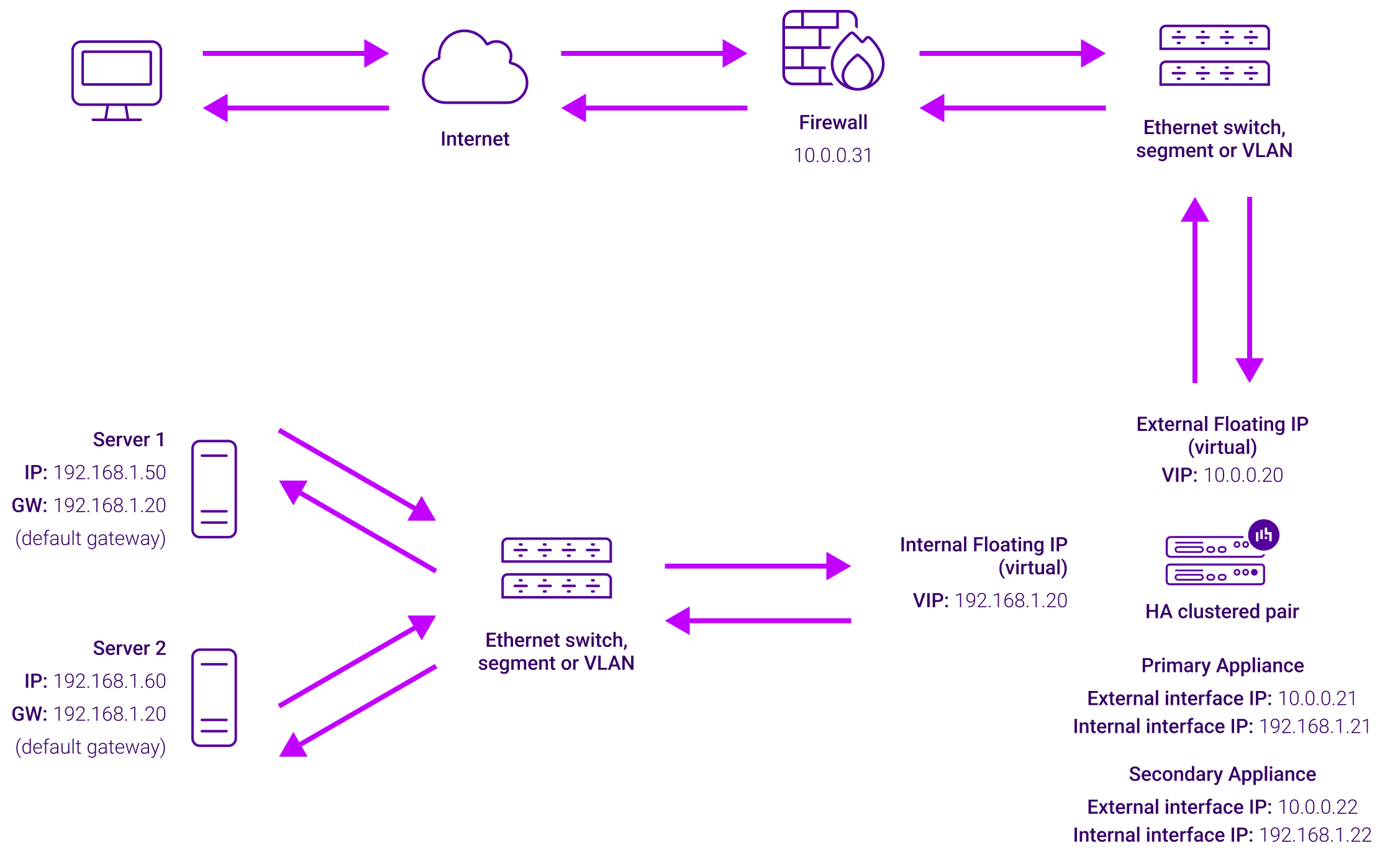
Load balancing topology
The load balancer translates all requests from the external Virtual Service to the internal Real Servers. Normally eth0 is used for the internal network and eth1 is used for the external network although this is not mandatory. If the Real Servers require Internet access, Autonat should be enabled using the WebUI option: Cluster Configuration > Layer 4 – Advanced Configuration, the external interface should be selected.
NAT mode can be deployed in the following ways:
- 2-arm (using 2 Interfaces), 2 subnets (as shown above) – One interface on the load balancer is connected to subnet1 and the second interface and Real Servers are connected to subnet2. The VIP is brought up in subnet1. The default gateway on the Real Servers is set to be an IP address in subnet2 on the load balancer. Clients can be located in subnet1 or any remote subnet provided they can route to the VIP.
- 2-arm (using 1 Interface), 2 subnets – same as above except that a single interface on the load balancer is allocated 2 IP addresses, one in each subnet.
- 1-arm (using 1 Interface), 1 subnet – Here, the VIP is brought up in the same subnet as the Real Servers. For clients located in remote networks the default gateway on the Real Servers must be set to be an IP address on the load balancer. For clients located on the same subnet, return traffic would normally be sent directly to the client bypassing the load balancer which would break NAT mode. To address this, the routing table on the Real Servers must be modified to force return traffic to go via the load balancer – For more details on ‘One-Arm NAT Mode’ refer to the administration manual.
If you want Real Servers to be accessible on their own IP address for non-load balanced services, e.g. SMTP or RDP, you will need to setup individual SNAT and DNAT firewall script rules for each Real Server or add additional VIPs for this – please refer to the administration manual for more details.
NAT mode is transparent, i.e. the Real Server will see the source IP address of the client. Port translation is possible in NAT mode, i.e. VIP:80 –> RIP:8080 is possible.