Load balancing Laurel Bridge Compass
Updated on March 24, 2026
•
Published on July 26, 2024
Benefits of load balancing Laurel Bridge Compass
Load balancing Laurel Bridge Compass Routing Workflow Manager offers several key benefits for healthcare organizations managing medical imaging data, including high availability, optimal performance, and enhanced scalability:
- High Availability (HA): This is arguably the most critical benefit in a healthcare setting. The load balancer constantly monitors the health of the Compass servers and automatically redirects all incoming DICOM/HL7 traffic away from a failed or under-performing server to a healthy one. This ensures zero-interruption to the medical imaging routing workflow for critical services.
- Optimal performance: By intelligently distributing the high volume of incoming medical imaging studies (DICOM images and HL7 messages) across multiple Compass servers, the load balancer prevents bottlenecks. This maintains stable, low-latency performance, ensuring studies are routed and delivered to radiologists and specialists as quickly as possible.
- Scalability: Load balancing allows the system to be horizontally scaled. When traffic increases, you can simply add more Compass servers to the backend pool. This ensures the imaging workflow can grow seamlessly to support the demands of the largest integrated health systems without service degradation. It also facilitates non-disruptive maintenance by allowing individual servers to be taken offline for upgrades without affecting overall service availability.
About Laurel Bridge Compass
Laurel Bridge Compass Routing Workflow Manager automates the ingestion, distribution, tracking, and access to medical imaging studies across disparate systems and locations, empowering healthcare organizations of all sizes to easily build and manage a scalable imaging workflow layer that enhances interoperability between PACS, VNA, and clinical IT environments.
It acts as a router for DICOM images/messages and HL7 version 2.x messages and is able to route from one or more Sources to one or more Destinations.
Why Loadbalancer.org for Laurel Bridge Compass?
This deployment guide isn’t theoretical; it has been field tested and rigorously validated by Laurel Bridge experts. This means you can be completely confident that the solution described is robust, reliable, and backed by the real-world operational experience of a global leader in healthcare technology.
Loadbalancer’s intuitive Enterprise Application Delivery Controller (ADC) is also designed to save time and money with a clever, not complex, WebUI.
Easily configure, deploy, manage, and maintain our Enterprise load balancer, reducing complexity and the risk of human error. For a difference you can see in just minutes.
And with WAF and GSLB included straight out-of-the-box, there’s no hidden costs, so the prices you see on our website are fully transparent.
More on what’s possible with Loadbalancer.org.
How to load balance Laurel Bridge Compass
The load balancer can be deployed in four fundamental ways: Layer 4 DR mode, Layer 4 NAT mode, Layer 4 SNAT mode, and Layer 7 Reverse Proxy (Layer 7 SNAT mode).
For Laurel Bridge Compass, Layer 4 SNAT is recommended.
Virtual service (VIP) requirements
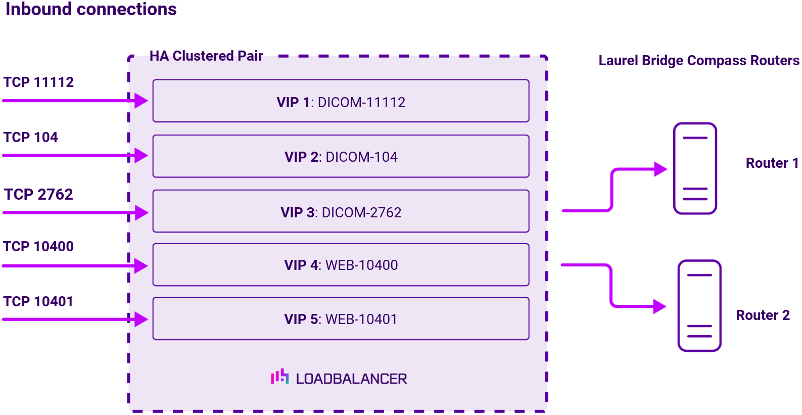
To provide load balancing and HA for Laurel Bridge Compass, the following VIPs are required:
| Ref. | VIP Name | Use | Mode | VIP Port(s) | Persistence Mode | Health Check |
|---|---|---|---|---|---|---|
| VIP 1 | DICOM-11112 | DICOM | Layer 4 SNAT | 11112 | None | External Script |
| VIP 2 | DICOM-104 | DICOM | Layer 4 SNAT | 104 | None | External Script |
| VIP 3 | DICOM-2762 | DICOM TLS | Layer 4 SNAT | 2762 | None | Connect to Port |
| VIP 4 | WEB-10400 | HTTP | Layer 4 SNAT | 10400 | Source IP | Connect to Port |
| VIP 5 | WEB-10401 | HTTPS | Layer 4 SNAT | 10401 | Source IP | Connect to Port |
Load balancing deployment concept
Once the load balancer is deployed, clients connect to the Virtual Services (VIPs) rather than connecting directly to one of the Laurel Bridge Compass routers. These connections are then load balanced across the Laurel Bridge Compass routers to distribute the load according to the load balancing algorithm selected:
About Layer 4 SNAT mode load balancing
Layer 4 SNAT mode is a high performance solution, although not as fast as Layer 4 NAT mode or Layer 4 DR mode. The image below shows an example network diagram for this mode:

Real Servers in the cluster can be on any accessible network including across the Internet or WAN.
Layer 4 SNAT mode is not transparent, an iptables SNAT rule translates the source IP address to be the load balancer rather than the original client IP address. Layer 4 SNAT mode can be deployed using either a one-arm or two-arm configuration. For two-arm deployments, eth1 is typically used for client side connections and eth0 is used for Real Server connections, although this is not mandatory since any interface can be used for any purpose. Requires no mode-specific configuration changes to the load balanced Real Servers.
Port translation is possible with Layer 4 SNAT mode, e.g. VIP:80 → RIP:8080 is supported. You should not use the same RIP:PORT combination for Layer 4 SNAT mode VIPs and Layer 7 Reverse Proxy mode VIPs because the required firewall rules conflict.